Wiring and installation instructions DLB, CLB, and DCLB boards, manufactured by Control Tech USA, Inc.
Features of circuit boards may or may not include depending on model:
- Two or Four data input lines rated at 5, 12, 30, or 35 volts dc depending on model.
- Two or four communication lines for in/out or T wiring schemes.
- Two data lines and two communication lines.
- Five levels of lightning protection for each line.
Installation, wiring, and feature operating instructions:
- Circuit board mounting.
- Position the board in the desired location using the board itself or the enclosed drill template.
- Secure the drill template to the mounting surface using tape, then center punch each hole for drilling. Drill each hole with a 3/16 drill bit.
- Push the nylon standoffs through the holes. Make sure you here or feel a slight snap indicating the standoffs are securely in place.
- Push board onto the standoffs and again listen or feel for the slight snap.
- Wiring instructions.
P1 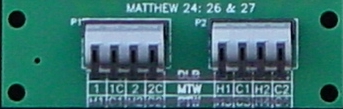 P2
P2
Bottom of board
Terminals P1 and P2, located at the bottom of the board, are for the field side wires.
Top of Board
Terminals P4 and P5, located at the top of the board, are for the controller side wires.
P4 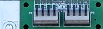 P5
P5
- Data Lines
- Viewing the lines as a pair, each with a number matched with the same number followed by a C designating common. i.e. 1 and 1C
- Connect the first data devise such as a flow meter to the first input line pair of P1 designated by 1 and 1C. Connect the Hot or (+) lead to terminal 1. Connect the Common or (-) or Ground lead to terminal 1C. For the remaining devices connect them by devise to 2 & 2C of P1, 3 & 3C, and 4 & 4C of P2, depending on your model, just as stated above for 1 and 1C.
- Connect the controller or monitor to 1 & 1C of P4. Connect the Hot or (+) lead to terminal 1. Connect the Common or (-) or Ground lead to terminal 1C. For the remaining devices connect them by devise to 2 & 2C of P4, 3 & 3C, and 4 & 4C of P5, depending on your model, just as stated above for 1 and 1C.
- DCLB boards will use only the first two channels, located in P1 and P4, for data line connections. Do not connect communication wires to these channels, as the board will be damaged!
- Communication lines or Two wire path
- Again, viewing the lines as a pair, each pair designated with an H and C for Hot and Common and a number to identify the channel. For the first communication line pair, connect the incoming Hot lead to H1 of P2, and the incoming Common lead to C1 of P2. For the remaining communication lines, connect them to H2 & C2 of P2, H3 & C3, and H4 & C4 of P5, depending on your model, just as stated above for H1 and C1. For example, the two wire path could come in from the field on H1 and C1, connect to controller then exit back out through H2 and C2. You have the choice of looping the two wire path or wiring it up in a T configuration where the path is Teed off into the board and up in to the controller or other devise.
- If you are running an earth ground lead along with the two wire path, connect it to the Ground lug or other earth ground source.
- DCLB boards will use only the last two channels, located in P2 and P5, for communication line connections. As mentioned above in Data line step iv, do not connect communication wires to the first two channels, as the board will be damaged!
- Grounding. Having a properly installed and operating earth grounding system is vital to the operation of the boards lightning protection devises. Control Tech USA, Inc. requires the grounding system to measure 10 ohms or less but preferably 5 ohms or less. Control Tech USA, Inc. has as part of its product line an excellent earth grounding kit and an earth ground resistance meter. Regardless of what type of grounding system used, it must be connected to the ground lug located at the top left of the board. It is best to use 6-10 gage solid conductor wire to connect the grounding system to the ground lug, and the shorter and straighter the wire the better. Additionally, the ground lug can be loosened and rotated 180 degrees and retightened in order to facilitate ease of wiring.
- Lightning Protection
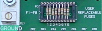 F1-F8
F1-F8
- The lightning protection devises on the boards will auto-reset, provided they are not damaged, with the exception of the resistive fuses located in the sockets at the upper center of the board.
- To test the fuses, using a volt ohm meter. Each fuse in the data lines will measure 0 ohms +/- 5%. For the communication lines, 1 ohm +/- 5%. Any other reading indicates a bad fuse. Indicators of a bad fuse are the data has stopped being received, communications have stopped, or the fuse is discolored and/or physically damaged.
- Each fuse is user replaceable. If a fuse is determined to be bad, simply pull out the bad fuse and replace it with a good one (this may require the use of a set of needle nose pliers). Additional fuse packs can be purchased from Control Tech USA, Inc. as part number CTU-DFP for the data lines and CTU-FP for the two wire path. One of each fuse pack should come with your board.
There may be some unusual circumstances arise in some installations. If you need technical assistance please do not hesitate to contact us.
© Control Tech USA, Inc 2005